High-Pressure Strand Burner Facility
The high-pressure strand burner at TAMU became operational in 2005. As seen in the schematic below, this strand burner is capable of pressures in excess of 5000 psia (34.5 MPa) and contains the infrastructure for operating remotely. This infrastructure includes electronically controlled pneumatic fill and exhaust valves along with remote ignition. Additionally, the entire strand burner structure is located behind blast walls. The strand burner is rated at 8000 psia (55.2 MPa) but most experiments are below 5000 psia. Inert gas, either Nitrogen or Argon, is used to pressurize the vessel for all propellant experiments. The vessel consists of a steel, cylindrical test chamber with an inner diameter of 94 mm (3.70 in) and a height of 203 mm (8.00 in) along with 3 windows spaced 90° apart. These windows allow for several different optical diagnostics such as spectroscopy and high-speed videos. An additional window made of zinc sulfide (ZnS) is located at the top of the burner. Laser light at 10.6 μm from a 100-W CO2 laser can be passed through this upper window for experiments where the cw laser is used to ignite the propellant samples. An image of the high-pressure strand burner is shown below.
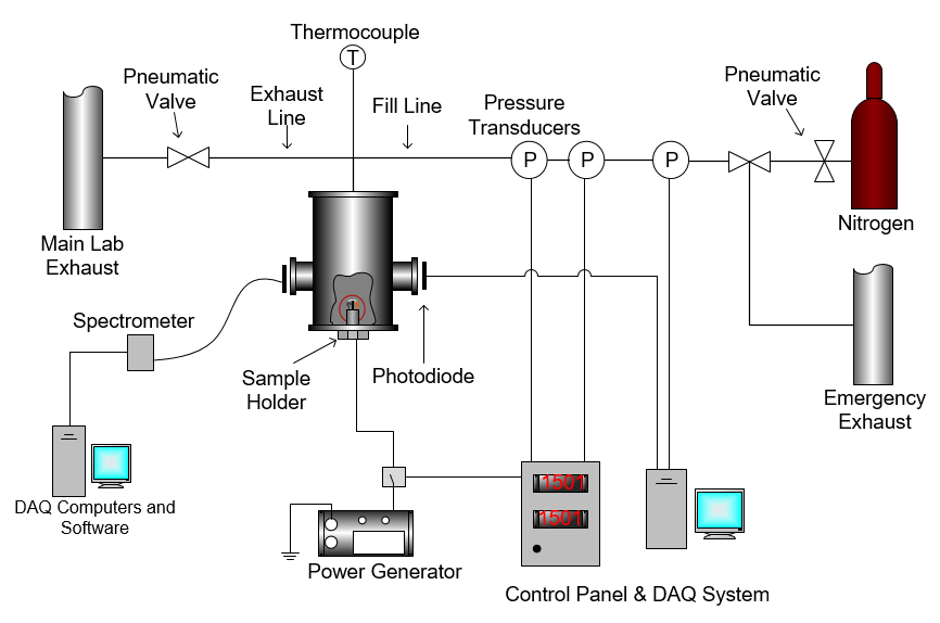
Schematic of high-pressure strand burner facility at TAMU.
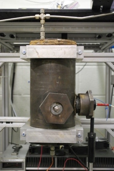
Photograph of the high-pressure strand burner facility at TAMU.
Propellant sample ignition for most experiments where precise ignition timing is not important is done with a nichrome wire. The nichrome wire is strung across the propellant samples between two leads. Current is sent through the wire by a remotely latching a relay. The sample holder is a modified, 1-in-diameter bolt. This design is simple to remove and remount while being robust enough to handle the high fill pressures. A similar sample holder is used for pellet and liquid propellant testing, just modified for each sample size. The figure below provides sample holder schematics for solid composite and liquid propellant testing.
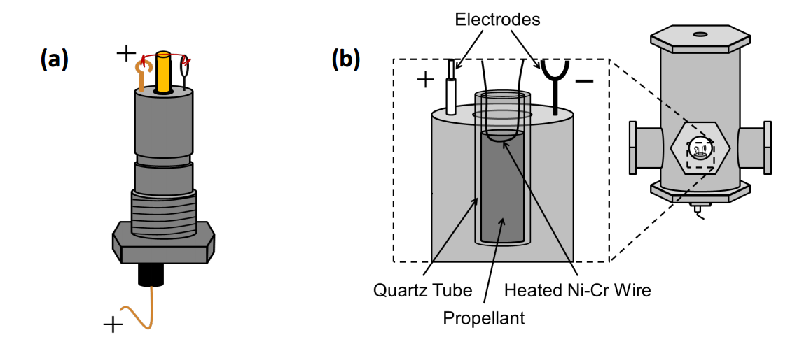
Propellant holder views. a) Solid composite propellant holder/bolt and wiring; b) Holder for a typical liquid propellant test showing the quartz tube and placement of ignition wire.
Common diagnostics routinely used in this facility include, but are not limited to, a pressure transducer, a digital video camera, a spectrometer (Ocean Optics USB2000), a high-speed Si photodiode detector (New Focus), and a Photron FASTCAM SA3 digital high-speed cameral capable of up to 120,000 fps. Burning-rate information from the pressure transducer and photodiode are collected by a high-speed, computer-based data acquisition system from Gage Applied Sciences (using Gagescope software) capable of 10 MHz sampling at 16-bit resolution.
Very-High-Pressure Strand Burner Facility
A second, constant-volume, very-high-pressure strand burner was designed and installed at TAMU in 2016. The basic design was primarily based on the original strand burner facility as described previously. However, this second burner doubles the normal operating pressure with the ability to safely test up to 10,000 psia (68.9 MPa), with a maximum design pressure of 15,000 psia (103.4 MPa). The design includes a cylindrical main body of 17-4PH stainless steel, two endcaps, and a bolt which is used as the sample holder. The main body is 30.48 cm (12 in) long with an outer diameter of 19 cm (7.5 in) and inner diameter, 9.6 cm (3.77 in), offering a wall thickness of 4.75 cm (1.87 in). Both threaded endcaps are 3.81 cm (1.5 in) thick with 7.6 cm (3 in) of 4.0-4 UNC-sized threads, making the overall length 38.1 cm (15 in). The top endcap contains two ports, one for pressurization and the other for a thermocouple to measure the initial temperature when performing temperature sensitivity. Photographs of the facility along with a schematic diagram are shown below.
Since compressed gases such as N2 only come in bottles at a maximum pressure of 6000 psia (41.4 MPa), an air-supplied Haskel AG-75 gas booster is used to compress the pressurizing gas to higher pressures than 6000 psia when needed. To avoid over-pressurization, the air supplied to the gas booster is controlled remotely via a solenoid valve attached to the line. Additionally, both filling and venting are executed remotely by actuating solenoid-operated, normally closed pneumatic valves. All testing is performed remotely and the strand burner facility is located behind blast walls.
In addition to very-high-pressure burning rate testing, the second strand burner facility was also designed for extreme hot and cold temperature sensitivity testing. The facility is capable of temperatures ranging from -88°F (-66°C) to 194°F (90°C) using a So-Low Freezer and heating tape, respectively. For low temperatures, the entire strand burner is placed horizontally in the So-Low Freezer, which has a specially designed mounting and gas delivery system inside. Heated experiments are performed by wrapping the vessel with heating tape and insulation. The heating tape has a feedback control system for maintaining a set temperature. The sample holder is loaded while cooling and heating to ensure constant expansion and contraction of material.
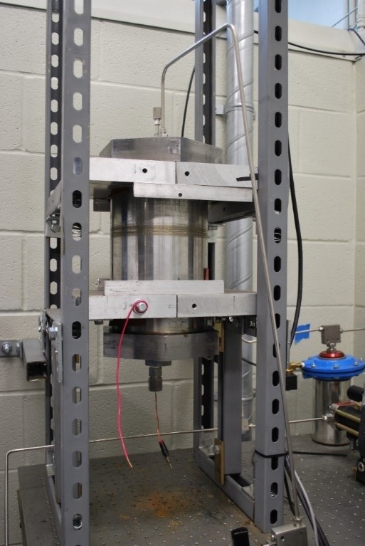
Photograph of very-high-pressure strand burner.
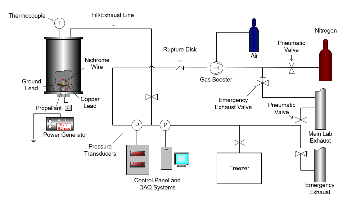
Schematic diagram of very-high-pressure strand burner facility.
