The high-pressure shock tube facility at the Petersen research group consists of the shock-tube hardware, control system, data acquisition system, vacuum section, and the velocity detection system. A schematic of the gas handling system and the shock tube in both the conventional and long test time configuration is given in the below figure. With this shock tube, we are able to reach a range of post-shock conditions of 600- 4000 K and a pressure up to 100 atm.
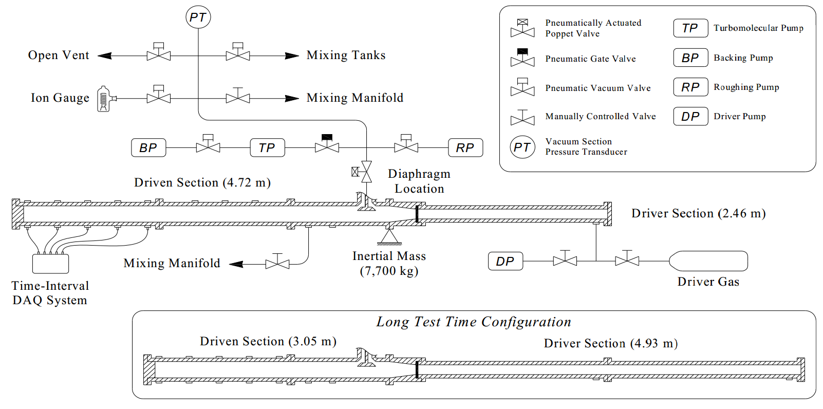
Schematic of the High-Pressure Shock Tube facility
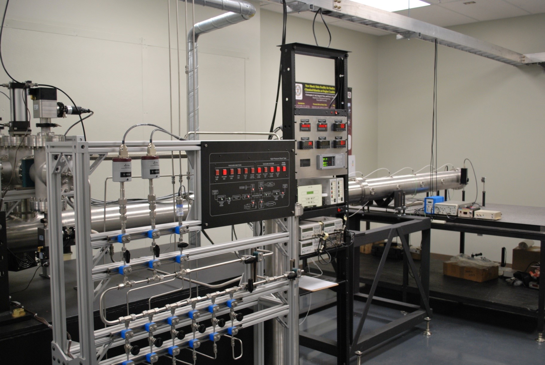
Image of the High-Pressure Shock Tube at Texas A&M.
In its conventional setup, the stainless steel shock tube has a 4.72-m long driven section with an inner diameter of 15.24 cm and a 2.42-m driver section with an inner diameter of 7.62 cm. A driver extension can be used to achieve a driver length of 4.93-m which allows increasing test times. The shock tube is also equipped with a large poppet valve (shown in the figure above) which allows for a large-area access to the shock tube. This feature enables the quick turnaround of experiments. The vacuum section consists of two pumping systems rated for use at both atmospheric (roughing pump, Agilent DS402) and high-vacuum (Turbomolecular pump) pressure. With this combination of pumps, a vacuum pressure of around ~1×10⁻⁵ torr is achieved before each experiment. Three pressure measurements devices are used in this facility which have a range of 0-100 torr (MKS 631D11TBFP), 0-1000 torr (MKS 631D12TBFP), and 0-250 psi. To measure the incident shock velocity, five piezoelectric pressure transducers PCB P113A are located along the last 1.8 m of the driven section.
To accommodate gas-phase testing of low-vapor pressure fuels, the shock tube has been fitted with custom-made heating jackets composed of 5 independently controlled elements. The jackets were supplied by BriskHeat and can reach temperatures up to 200 °C. Additional heating elements and fiberglass insulation were applied on the mixing tank and manifold to prevent any possible fuel condensation. The heating jackets were calibrated to reach uniform temperature distribution along the last 3 m of the driven section which is shown in the figure below for several set-points. The temperature variation was limited to ±1 °C for the set-points of 50, 75, and 100 °C, while a limit of ±2 °C was observed for the 150 °C set-point.
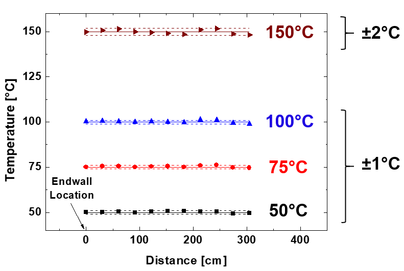
Uniform temperatures along the heated driven section of the HPST
Typically, gas mixtures are prepared in a separate 74-L high purity stainless steel mixing tank that is also equipped with serval heating jackets. The mixing tank is connected to the shock tube through a stainless steel manifold that is also heated using heating tapes and covered with fiberglass insulation to prevent any possible fuel condensation during the filling process. The manifold is also equipped with several connection points to allow access of external gas cylinders. In the case of preparing low-vapor pressure fuel mixtures, the mixing tank has a septum/needle system which allows for direct injection of the liquid fuel. Images of the heated shock tube, mixing tank, and manifold are shown below.
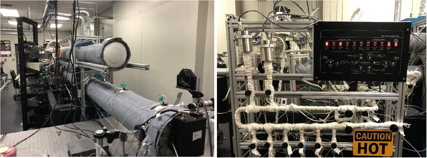
Images of the heating system on the shock-tube driven section, the mixing tank, and the manifold