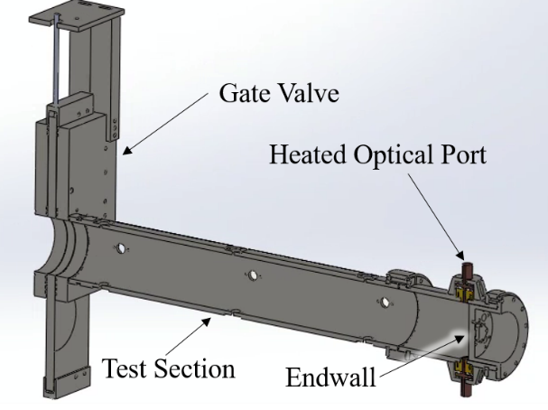
Traditionally, the study of low-vapor pressure fuels in shock tubes has been conducted using the heated shock-tube method, such as in previous works by Rotavera and Petersen [1, 2] and Horning et al. [3]. Due to the low vapor pressures of some heavy hydrocarbons, they are unable to be mixed reliably as a gaseous component at standard atmospheric temperatures and pressures using traditional shock-tube mixing methods. Instead, such fuels must either be heated so as to be held in the gas phase, or physically suspended as an aerosol while being introduced into a shock-tube mixture [4-6]. In our aerosol shock tube located at the TAMU Qatar campus, heavy hydrocarbons are suspended in an aerosolized mixture and constrained to a region near the endwall of the shock tube prior to shock wave passage. A diagram of the gate valve setup is shown in the Figure below. Local management of this facility is in collaboration with Dr. Bing Guo from the Department of Mechanical Engineering at TAMU Qatar.

A diagram of the gate valve located within the driven section for constraining the aerosol near the endwall
Aerosol Shock Tube Facility Modifications
The aerosol shock tube facility was constructed for the ultimate purpose of studying the combustion chemistry of heavy hydrocarbons in the form of aerosolized liquids. Although the study of aerosolized fuels requires nuanced modification of traditional shock tubes, the main components of the shock-tube facility remain the same. In fact, the conditions that this aerosol shock tube can achieve, up to 4000 K, and 100 atm, are similar to those in our High Pressure Shock Tube. Furthermore, the majority of the design of the shock tube developed for this study is inspired by the High Pressure Shock Tube facility in our laboratory, with details given by Aul et al. [7] and Petersen et al. [8]. In addition to the recycling of various designs for the aerosol shock tube, several hardware modifications have been made to the current facility that differ from other designs in our group.
In regard to design modifications of the aerosol shock tube facility compared to our other facilities, the current facility has a driver section diameter larger than those of other facilities. Consequently, the nozzle between the driver and driven section is converging. The driver diameter is 7.625” (19.37 cm) and has configurable lengths of up to roughly 6.6 m. As well as having a converging nozzle, the diaphragm breech section is equipped so that it can be operated as a double-diaphragm chamber where the shock wave is initiated by evacuating the space between the diaphragms instead of filling the driver section until diaphragm breakage. This filling technique enables greater consistency of the P4 pressure in the driver section and ultimately more control of the P5 pressure behind the reflected shock wave.
In addition to the driver section modifications, driven-section upgrades have been included in the design of the new facility. The shock tube is able to operate as a constrained reaction volume (CRV) shock tube, which was introduced by Hanson and coworkers [9] and improved by Campbell and coworkers [10]. CRV operation is achieved with the aid of a gate valve located roughly 1.25 m from the endwall of the driven section. As previously discussed, the gate valve can also accommodate the use of aerosol mixtures by restricting the aerosol into the region near the endwall for the shock tube. This technique enables faster aerosol filling times and avoids complications resulting from aerosol settling in comparison to filling the entire driven section of the shock tube with an aerosolized mixture. The ports in the sidewall region near the driven section endwall are also equipped with heated windows to minimize window fouling from aerosol deposition on the window surfaces. Heating of the windows allows more-accurate interpretation of laser spectroscopy measurements in the shock tube, as was found by Davidson and coworkers [4].
During a shock experiment, the conditions behind the incident shock wave in the bulk flow of the tube will cause the aerosolized fuel to evaporate, but fuel droplets or fuel vapor that come into contact with the region near the windows will condense and stick to the window due to the window (and shock-tube sidewalls) behaving as a heat sink over the time scales experienced in typical shock-tube experiments. Avoiding window fouling is critical to obtaining accurate measurements of fuel concentration behind the incident shock wave.
Aerosol Generation Facility
For the production of aerosols, another apparatus is required in addition to the shock-tube setup itself. An aerosol generation tank external to the shock tube, equipped with an ultrasonic nebulizer similar to that used by Haylett et al. [5] and Davidson et al. [4], generates a mixture of uniformly spaced droplets (as defined in [5]) that can then be drawn into the shock tube. The mixture is transferred to the shock tube by placing an evacuated dump tank connected with a 10-mm ball valve downstream of the shock tube and using a pressure differential to draw the aerosolized mixture from the aerosol generation tank through the shock tube towards the dump tank. This method of entrainment is similar to that used by Haylett and coworkers and Davidson and coworkers, respectively [4, 5].
One key difference between this facility and the cited works from Stanford University is that the method of injection between the aerosol generation tank and the shock-tube test section is different. For the current work, the tube between the aerosol generation tank and test section is inserted into the shock tube at a sidewall port location near the endwall during filling and is retracted after filling. This method of aerosol introduction enables various types of injector nozzle geometries to be tested to determine an optimum design. The nebulizer has an oscillation frequency of 1.7 MHz, generating a droplet distribution with a mass-mean diameter near 4.5 μm. The tank volume is roughly 27 L and is connected to the driven section of the shock tube by a 1.5-inch (3.81-cm) fill line (ID = 1.26 in).

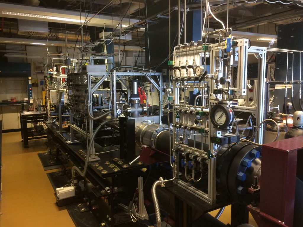
Picture of the Aerosol Shock Tube at the TAMU Qatar campus
References
[1] B. Rotavera and E. L. Petersen, “Shock-Wave Induced Ignition of Normal Undecane (n-C11H24) and Comparison to Other High-Molecular-Weight n-Alkanes,” 28th International Symposium on Shock Waves, 2012; Berlin, Heidelberg: Springer Berlin Heidelberg.
[2] B. Rotavera and E. L. Petersen, “Model predictions of higher-order normal alkane ignition from dilute shock-tube experiments,” Shock Waves, Vol. 23, 2013, pp. 345-359. doi: 10.1007/s00193-012-0387-6.
[3] D. C. Horning, D. F. Davidson, and R. K. Hanson, “Study of the High-Temperature Autoignition of n-Alkane/O/Ar Mixtures,” Journal of Propulsion and Power, Vol. 18, 2002, pp. 363-371. doi: – 10.2514/2.5942.
[4] D. F. Davidson, D. R. Haylett, and R. K. Hanson, “Development of an aerosol shock tube for kinetic studies of low-vapor-pressure fuels,” Combustion and Flame, Vol. 155, 2008, pp. 108-117. doi: 10.1016/j.combustflame.2008.01.006.
[5] D. R. Haylett, D. F. Davidson, and R. K. Hanson, “Second-generation aerosol shock tube: an improved design,” Shock Waves, Vol. 22, 2012, pp. 483-493. doi: 10.1007/s00193-012-0383-x.
[6] B. Rotavera, N. Polley, E. L. Petersen, K. Scheu, M. Crofton, and G. Bourque, “Ignition and Combustion of Heavy Hydrocarbons Using an Aerosol Shock-Tube Approach,” ASME Paper GT2010-22844, Proceedings of ASME Turbo Expo 2010: Power for Land, Sea and Air; 2010; Glasgow, UK. doi: 10.1115/GT2010-22844.
[7] C. J. Aul, W. K. Metcalfe, S. M. Burke, H. J. Curran, and E. L. Petersen, “Ignition and Kinetic Modeling of Methane and Ethane Fuel Blends With Oxygen: A Design of Experiments Approach,” Combustion and Flame, Vol. 160, 2013, pp. 1153-1167. doi: 10.1016/j.combustflame.2013.01.019.
[8] E. L. Petersen, M. J. A. Rickard, M. W. Crofton, E. D. Abbey, M. J. Traum, and D. M. Kalitan, “A Facility for Gas- and Condensed-Phase Measurements Behind Shock Waves,” Measurement Science and Technology, Vol. 16, pp. 1716-1729. doi: 10.1088/0957-0233/16/9/003.
[9] R. K. Hanson, G. A. Pang, S. Chakraborty, W. Ren, S. Wang, and D.F. Davidson, “Constrained reaction volume approach for studying chemical kinetics behind reflected shock waves,” Combustion and Flame, Vol. 160, 2013, pp. 1550-1558. doi: https://doi.org/10.1016/j.combustflame.2013.03.026.
[10] M. F. Campbell, A. M. Tulgestke, D. F. Davidson, and R. K. Hanson, “A second-generation constrained reaction volume shock tube,” Review of Scientific Instruments, Vol. 85, 2014, pp. 055108. doi: 10.1063/1.4875056.
