• Skip to primary navigation
  • Skip to main content
  • Skip to primary sidebar
  • About Us
  • Research
    • Gas Dynamics & Chemical Kinetics
      • Shock-Tube Physics
      • Shock-Tube Kinetics
        • Ignition Delay Time
        • Speciation
      • Chemical Kinetics Modelling
      • Fundamental Flame Propagation
        • Laminar Flame Propagation
        • Turbulent Flame Propagation
      • Detonations and Explosions
    • Rocket Propellants and Energetics
      • Composite Solid Propellants
      • Liquid Monopropellants
      • Hybrid Rockets and SFRJ
      • Gas Generant Systems
    • Optical Diagnostics and Spectroscopy
      • Direct Laser Absorption
        • Fixed-Wavelength Diagnostics
        • Scanned-Wavelength Diagnostics
      • Chemiluminescence
      • Planar Laser Induced Fluorescence
      • High-Speed Schlieren and Shadowgraph
    • Additional Research
  • People
    • Principal Investigator
    • Research Scientists
    • Post-Doctoral Researchers
    • Ph.D. Students
    • M.S. Students
    • Undergraduate Students
    • Former Students
  • Facilities
    • Turbomachinery Laboratory
    • Shock Tubes
      • High-Pressure Shock Tube
      • Aerospace Shock Tube
      • Square Shock Tube
      • Aerosol Shock Tube
      • Detonation Tube
      • Aerospace Corporation Laboratory
    • Optical Diagnostics
      • Quantum Cascade Lasers
      • Tunable Diode Lasers
      • Gas lasers
      • High-Speed Imaging
      • Collaborator Diagnostics
    • Constant-Volume Combustion Vessels
      • HPHT Flame Speed Vessel
      • Turbulent Flame Speed Vessel
    • Propellant and Energetics Laboratory
      • Mixing and Manufacturing
      • High Pressure Strand Burner(s)
      • Hybrid Rocket Stand
      • Supporting Equipment and Diagnostics
      • Safety Testing
    • Unique Experiments
  • Publications
  • Patents
  • Gallery
  • News
  • Contact Us

Petersen Research Group

Texas A&M University College of Engineering

Hybrid Rocket Stand

The propellant and energetics laboratory houses a lab-scale hybrid rocket test stand capable of measuring key ballistic properties of potential fuel/oxidizer combinations for hybrid rocket and solid fuel ramjet applications. The combustion chamber section of the stand includes an injector bulkhead, an injector insert, a pressurized constant-volume chamber, and a nozzle bulkhead. An experimental schematic and representative images of the test stand are shown in the image below. The combustion chamber can house cylindrical solid fuel samples with lengths up to 12 cm and diameters as large as 3.3 cm. The modular design and lab-scale size of the chamber and fuel grains allow for rapid and economical testing of numerous fuel compositions in a short time scale.

Ballistic testing is initiated by the flow of oxidizer through the combustion chamber, typically gaseous oxygen (GOX), which is controlled by a pre-filled blowdown tank or by means of a programmable mass flow controller with flowrates up to 5 g/s. This mass flowrate translates to oxidizer mass fluxes as high as 200 kg/m2-s. Combustion processes are initiated by a solid propellant squib located in the pre-combustion chamber. The fuel sample is extinguished by termination of the oxidizer flow.

Key diagnostics include transient chamber pressure (250 psia) and rocket thrust, as well as the initial and final fuel grain masses and combustion port diameters. These parameters are typically utilized to calculate the average oxidizer mass flux, regression rate, mass loss rate, specific impulse, combustion efficiency, and specific impulse efficiency of a single motor firing. Advanced burn reconstruction methodologies are also utilized to compute transient fuel mass loss rates, regression rates, and combustion efficiencies. Additionally, condensed-phase combustion products are collected in the exhaust plume of the nozzle. The surfaces of post-firing fuel samples and the collected combustion products are imaged and analyzed for their atomic composition with advanced scanning electron microscopes (SEM) coupled with energy dispersive spectroscopy (EDS).

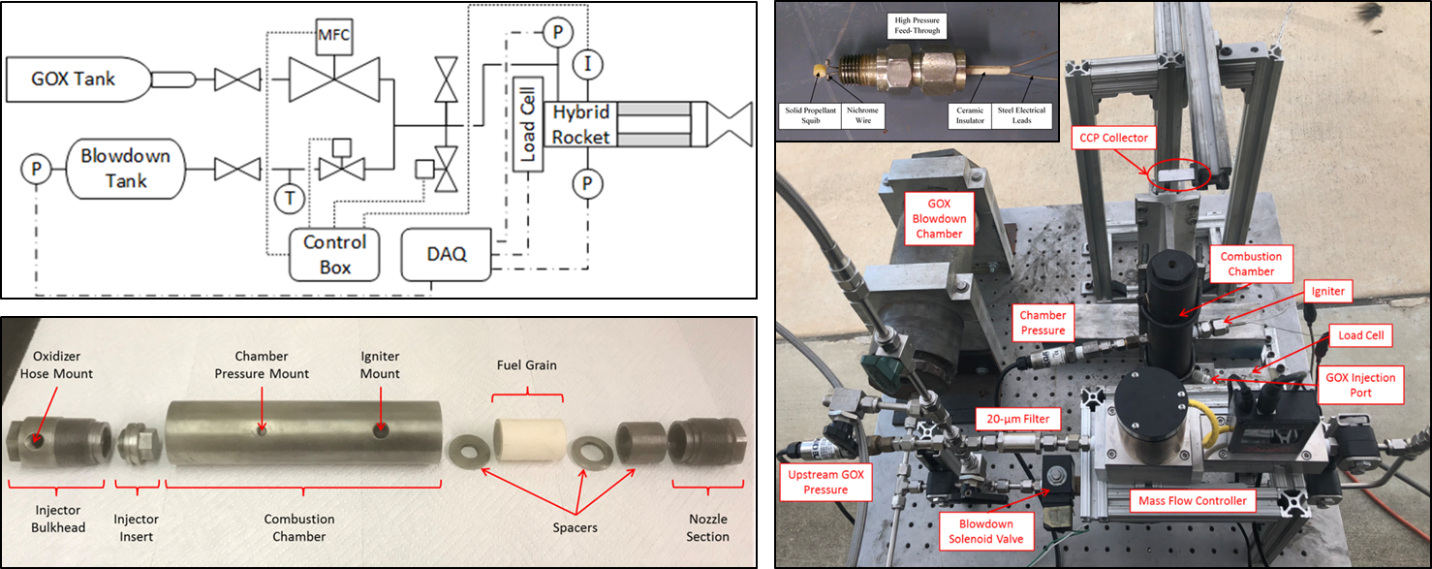
Hybrid rocket test stand. (top, left) Schematic representation of the test stand depicting key diagnostics and control systems. (bottom, left) Image of the expanded rocket combustion chamber depicting interchangeable components and a typical assembly. (right) Image of the test stand depicting key sub-systems.

Facilities

  • Turbomachinery Laboratory
  • Shock Tubes
  • Optical Diagnostics
  • Constant-Volume Combustion Vessels
  • Propellant and Energetics Laboratory
    • Mixing and Manufacturing
    • High Pressure Strand Burner(s)
    • Hybrid Rocket Stand
    • Supporting Equipment and Diagnostics
    • Safety Testing
  • Unique Experiments

© 2016–2023 Petersen Research Group Log in

Texas A&M Engineering Experiment Station Logo
  • College of Engineering
  • Turbomachinery Laboratory
  • J. Mike Walker ’66 Department of Mechanical Engineering
  • State of Texas
  • Open Records
  • Risk, Fraud & Misconduct Hotline
  • Statewide Search
  • Site Links & Policies
  • Accommodations
  • Environmental Health, Safety & Security
  • Employment