Shock tubes are ideal devices for studying combustion and chemical kinetics at high temperature and pressure. These devices produce these conditions by generating a shock wave to compress and heat the test gas (e.g. methane-air, etc.). A shock tube generates a shock wave using a section of high-pressure gas (referred to as driver section, usually filled with helium) and a section of low-pressure gas (driven section) separated by a diaphragm. Once the diaphragm ruptures, the driver and driven gases come into contact, creating a contact surface that acts as a piston compressing the test gas in the driven section and initiating shock wave propagation. The shock wave travels through the test gas in the driven section, then reflects from the closed endwall of the shock tube, causing further heating and compression of the test gas and stagnating it.
An x-t diagram (shown below) shows this process and depicts the region where the experiment occurs. The horizontal axis indicates position along the shock tube, and the vertical axis shows time elapsed since diaphragm rupture. Near the endwall (the far right in the x-t diagram) of the shock tube is an ideal environment for studying combustion processes at high temperature and pressure. Optical windows and pressure transducers are used in this region to track pressure, emission, and species concentrations in the test gas during the experiment.
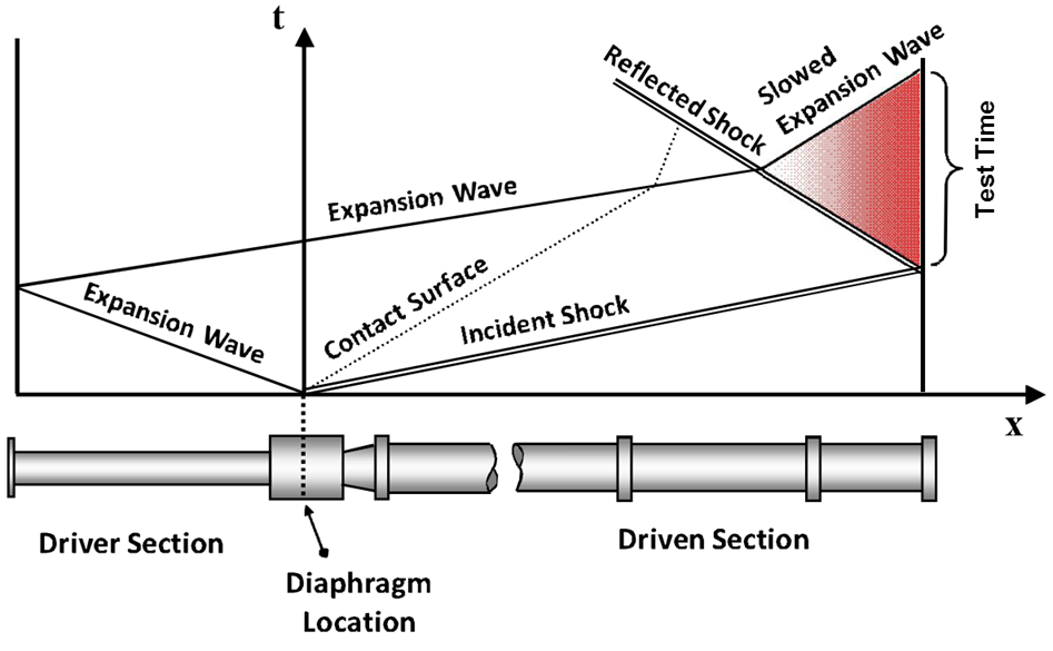
Typical shock tube x-t diagram.
Despite their many advantages and applications, several limitations are present when running shock-tube experiments, and a major limitation is the test time. As shown in the x-t diagram above, the test time is defined by the difference between shock wave reflection and the arrival of the expansion wave at the endwall. Several methods can be used to delay the expansion wave arrival, most obvious of which is to extend the driver section. Another method is to slow down the expansion wave by decreasing the sound speed of the driver gas by adding heavier gasses. In our laboratory, the shock tubes are configurable to test times upward of 12 ms.
Other limitations include non-ideal phenomena stemming from viscous effects within the shock tube. These effects depend highly on the test gas and the shock-tube geometry. Due to the relatively large inner diameter of our shock tubes, these viscous effects are minimized compared to other, smaller shock-tube facilities. Investigations have and are continuously being made to characterize and minimize these effects further within these shock tubes, and others, to maximize the data quality. Further information on work done in this laboratory on shock-tube physics is provided in the references below.
References:
[1] J. W. Hargis and E. L. Petersen, “Shock-Tube Boundary-Layer Effects on Reflected-Shock Conditions With and Without CO2,” AIAA Journal, Vol. 55, No. 3, 2017, pp. 902-912.
[2] A. R. Amadio, M. W. Crofton, and E. L. Petersen, “Test-Time Extension behind Reflected Shock Waves using CO2-He and C3H8-He Driver Mixtures,” Shock Waves, Vol. 16, No. 2, 2006, pp. 157-165.
[3] E. L. Petersen and R. K. Hanson, “Measurements of Reflected-Shock Bifurcation Over a Wide Range of Gas Composition and Pressure,” Shock Waves, Vol. 15, 2006, pp. 333-340.